Radial Shaft Seal Design Guidelines: Shaft and Housing Tolerances as per ISO/DIN Standards

ISO 286
DIN 3760/3761
Designing an efficient radial shaft sealing system requires a deep understanding of shaft and housing tolerances, surface finishes, materials, and fitment conditions. Proper application of these parameters ensures optimal sealing performance, minimal wear, and extended service life. Incorrect sizing, finish, or material selection can cause leakage, premature wear, or rotational failure. This guide explains the critical design elements of radial shaft seals—also known as oil seals—with a focus on ISO 286 and DIN 3760/3761 standards, including shaft and housing geometry, fits, and installation best practices.
Key Takeaways:
Explains the concept of clearance, transition, and interference fits
Shows how shaft and hole tolerances (H7, h8, g6, etc.) interact
Uses visual animations to explain how tolerances affect assembly
Includes examples related to bearing seats, seals, and mechanical design
Why Tolerances Matter
Proper tolerances ensure that the seal fits snugly and functions as intended. Incorrect tolerances can lead to leaks, premature wear, or even seal failure. Tolerances affect both the static fit (how tightly the seal sits in the housing) and the dynamic fit (how well the seal lip rides on the shaft).
Shaft Tolerance Guidelines
1.1 Shaft Diameter Tolerances

Shaft Diameter Tolerances
The shaft diameter must comply with ISO 286-2, typically using a maximum tolerance of h11. This standard ensures that the seal maintains the correct interference fit and prevents dynamic imbalance. Improper diametral tolerances may lead to oil leakage, improper sealing pressure, or excessive wear on the sealing lip.
Key Recommendation:
Use h11 tolerance class for shaft diameters for most industrial applications.
1.2 Shaft Lead-in Chamfer
A lead-in chamfer is crucial for safely and correctly installing the radial shaft seal. Without a properly designed chamfer, the sealing lip may become damaged or twisted during mounting. Appropriate tools specified in ISO 6194-3 should be used to prevent damage to the sealing lip during assembly. If a radius is used in place of a lead-in chamfer, the radius should be within the range of 1.8 mm to 3.0 mm
Best Practices:
Use a chamfer angle of 15° to 30°
Ensure the chamfer is smooth and free of burrs
Chamfer length should be adequate for easy seal entry


This prevents damage to the seal during installation and maintains correct alignment on the shaft.
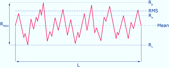
1.3 Shaft Surface Roughness
The shaft's contact surface with the sealing lip must meet precise roughness criteria. A poor surface finish can result in increased friction, wear, and sealing failure.

Recommended Roughness Range:
Ra: 0.2 – 0.8 µm
Avoid:
Spiral machining marks (which cause a pumping effect)
Pits, grooves, scratches, or any irregularities
As shaft speed increases, consider increasing the shaft hardness to reduce wear. Minor surface defects can rupture the lubricant film and break the meniscus at the seal interface, leading to leakage.
Housing Tolerance Guidelines
Equally important as the shaft is the housing bore, which holds the outer diameter of the radial shaft seal. Proper housing design ensures that the seal remains in position, maintains its shape, and performs reliably.
2.1 Housing Bore Tolerances

The housing bore should follow ISO tolerance standards to ensure a proper press fit of the outer seal casing. A tight and uniform fit prevents movement and leakage at the outer diameter.
Key Recommendation:
Use a H8 tolerance class (ISO 286-2) for housing bore dimensions
Improper housing tolerances can cause seal dislocation, misalignment, or bypass leakage around the outer edge.
2.2 Housing Bore Chamfer
Similar to the shaft, the housing bore should include a lead-in chamfer to ease the installation of the seal without damaging its outer coating or structure.

Best Practices:
Chamfer angle: 15° to 30°
Smooth and burr-free edges
This design detail avoids damaging the seal during press-fit installation and ensures consistent axial alignment.
2.3 Housing Bore Surface Roughness
The surface finish of the housing bore must also meet specific requirements to ensure effective sealing and prevent rotation of the seal in the housing. The axial surface roughness of the housing bore should be between Ra 1.6 µm and Ra 3.2 µm. For metal-cased seals, a lower surface roughness may be necessary. In such cases, the exact requirement should be mutually agreed upon by the manufacturer and the user.
Recommended Roughness:
Ra ≤ 3.2 µm
Too rough a surface may damage the outer casing of the seal, while too smooth a surface might not provide enough grip to hold the seal in place, especially under pressure or thermal expansion.
Seal Tolerances: Ensuring Proper Fit and Function
Proper dimensional tolerances are critical for reliable seal performance and long-term operation. Below is an overview of recommended tolerances for seal width and outside diameter (O.D.) based on industry standards such as DIN 3760 and ISO 6194. Radial shaft seals typically require:
Press fit in the housing (static fit)
Contact fit on the shaft (dynamic seal)
ComponentFit TypeInterferenceSeal ODPress fit (bore)0.2 – 0.5 mmSeal IDLip contactGentle, uniform pressure
3.1 Seal Width Tolerances (H)

Seal width plays an important role in proper seating and axial stability. The recommended tolerances for nominal seal width are summarized in
3.2 Seal Outside Diameter (O.D.) Tolerances
To ensure a secure interference fit between the seal and the housing bore (specifically for ferrous housings), the seal’s outside diameter is intentionally manufactured slightly larger than the housing bore. This prevents the seal from moving or slipping during operation.
The specific press-fit tolerances depend on:
The seal material (rubber-covered or metallic)
The design and O.D. size of the seal
These tolerances are defined in DIN 3760 and ISO 6194 standards. The applicable values can be found in Table 7 (not shown here), which outlines permissible deviations for various seal types and dimensions.

ISO Standards for Radial Shaft Seals
ISO 6194-1 – Rotary shaft lip-type seals – Part 1: Nominal dimensions and tolerances
Specifies key dimensions and tolerances for shaft seals (shaft diameter, housing bore, width, etc.).
ISO 6194-2 – Part 2: Design, material, and application guidelines
Provides recommendations for selecting materials, types of seals, and their applications.
ISO 6194-3 – Part 3: Storage, handling, and installation
Guidelines for how to properly store, transport, and install rotary shaft seals.
ISO 6194-4 – Performance test procedures for shaft seals
Methods to test seals for leakage, torque, and wear under defined conditions.
ISO 6194-5 – Identification code
Defines an identification system for shaft seals based on dimensions, material, and design.
ISO 4287 / ISO 4288 – Surface texture (roughness) parameters
Standards for surface roughness (Ra, Rz) measurement of shaft and housing.
ISO 1302 – Indication of surface texture in technical product documentation
Provides symbols and rules for showing surface finish requirements in technical drawings.
ISO 281 – Rolling bearings – Dynamic load ratings and rating life
While not directly a seal norm, relevant for seal design in bearing environments.
ISO 1940-1 – Mechanical vibration – Balance quality requirements
Important for rotating systems to ensure proper seal function under vibration.
DIN Standards for Radial Shaft Seals
DIN 3760 – Radial shaft seals – Dimensions and requirements
Specifies dimensions, material requirements, design forms (A, B, C, etc.), and performance criteria for rotary shaft seals used in machines.
DIN 3761 – Shaft seals – Part series for sealing systems
Deals with the arrangement and combinations of different sealing systems like shaft seals, V-rings, and labyrinth seals.
DIN 3762 – Installation and testing of rotary shaft seals
Provides guidelines for installing seals and testing them for leakage, wear, and pressure resistance.
DIN 3763 – High-pressure rotary shaft seals
Focuses on rotary shaft seals that can withstand high-pressure applications.
DIN 3764 – Radial shaft seals for special applications
Covers shaft seals used in aggressive media or extreme temperatures.
DIN ISO 286-1 / 286-2 – Geometrical product specifications (GPS) – ISO system of limits and fits
Defines fit classes (e.g., h11 for shafts, H8 for bores) essential for proper seal and component interaction.
DIN ISO 1101 – Geometrical tolerancing – Geometrical characteristics
Standard for geometric tolerances like roundness, concentricity, and coaxiality for shaft/housing alignment.
Conclusion:
A properly designed radial shaft seal system ensures longer machine life, reduced downtime, and optimal performance. Always follow ISO 286 and DIN 3760/3761 tolerance recommendations for shaft and housing dimensions. By combining correct surface finish, hardness, and interference fit, you can build sealing systems that are both durable and reliable. For engineers and designers, ISO and DIN standards for radial shaft seal tolerances ensure optimal performance, minimize wear, and extend service life. Correct tolerances in shaft diameter, housing bore, surface roughness, and chamfers are critical for both static and dynamic sealing performance.